

Post by phonogfp on May 27, 2010 18:50:05 GMT -6
As a supplement to the article that appeared in the June 2010 issue of The Sound Box, CAPS is pleased to present these additional photos of the 1894 Kammer & Reinhardt Gramophone Doll. Space limitations prevented these from being included in the article. We hope collectors will enjoy the additional detail shown in these views.
George P.
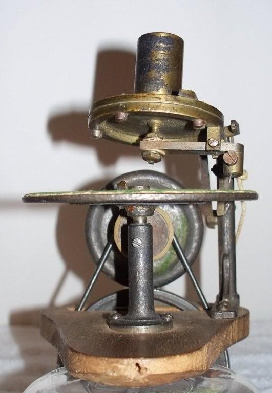
The mechanism removed from the doll’s body, front view.
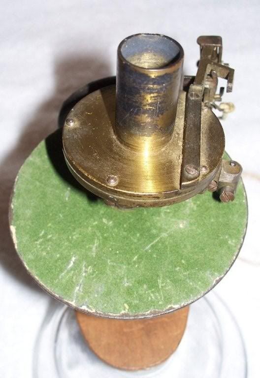
The mechanism from slightly above; note the sound box’s forked arm and the limit pin protruding upward within the tines of the fork. Lateral movement of the sound box is limited to the distance between the tines of the fork by this limit pin.
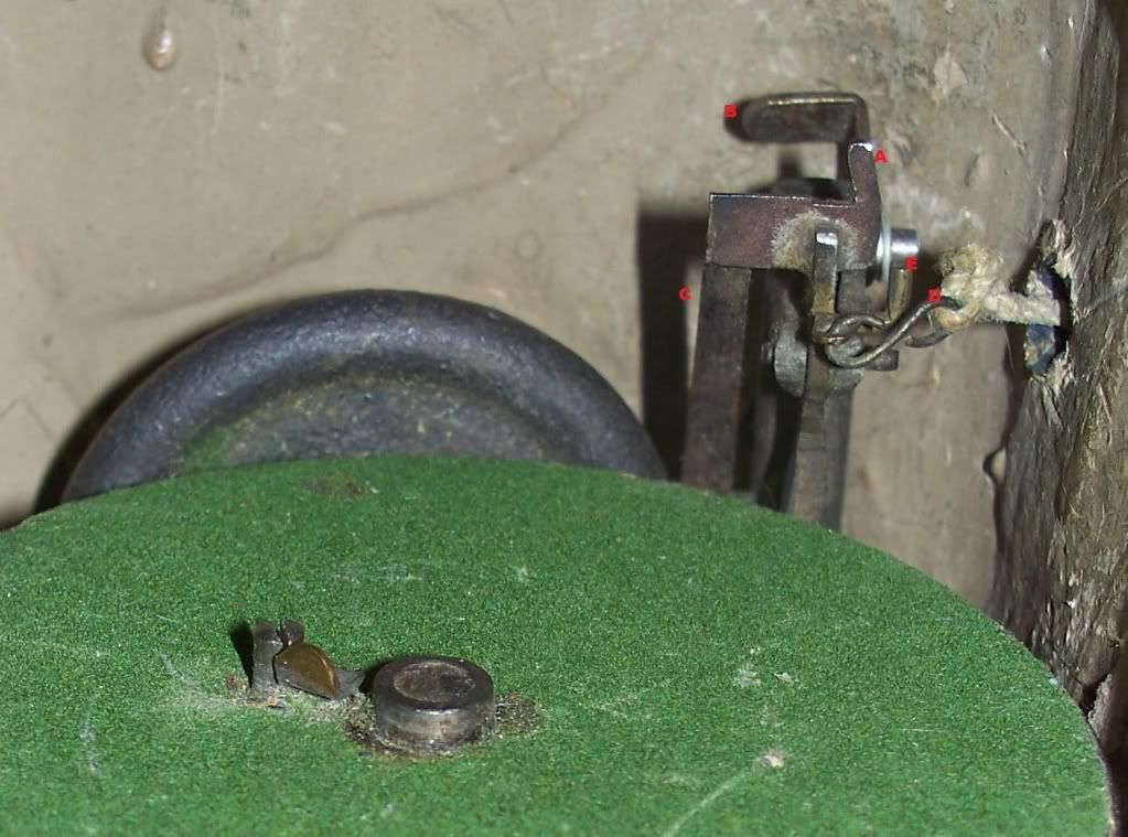
Detail of the sound box activation, return, and locking mechanism. "A" is the limit pin (part of the sound box rest) that contacts either inner surface of the forked arm of the sound box. This prevents the sound box from traveling beyond the sound groove into the label area. It also positions the sound box at the beginning of the sound groove when the sound box rest/limit pin is reset by pushing the brass button on the doll’s back. The shallow notch just to the left of limit pin “A” is where the sound box’s forked arm rests while in a locked position. When the string is pulled, the S-hook “D” pulls a spring-loaded hook to the right, allowing the sound box rest/limit pin “A” to fall forward and drop the sound box’s needle onto the record. "E" limits the movement of the hook that is pulled to the right by the string. "C" is a strip of spring steel that exerts forward pressure on the sound box rest. Pushing the brass button on the doll’s back forces the sound box rest & limit pin “A” back up to its locked position. "B" is an "L" shaped clamp that is brought forward to hold the sound box in place or pushed back (as shown) to allow its removal.
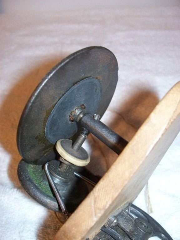
Detail of drive mechanism from the lower right side. A rubber friction pad added to the underside of the 3” turntable was one of the improvements embodied in the production model.
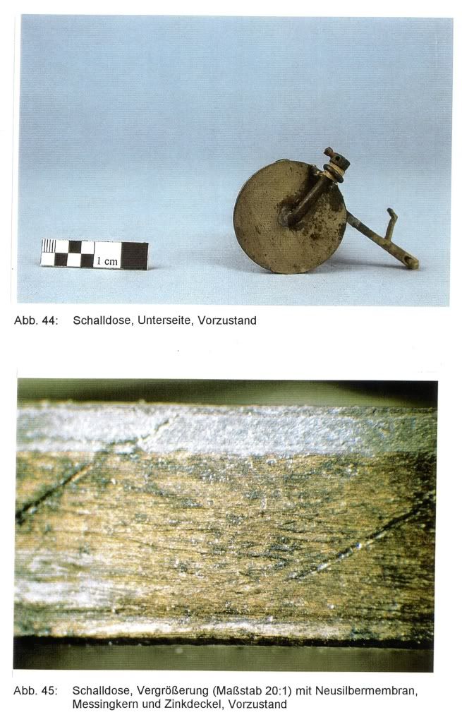
The 1890 prototype/sample Kämmer & Reinhardt Gramophone doll’s sound box. Compare this crude design with the 1894 production model in the first two illustrations above. (Courtesy of Christina Siegert)
George P.
The mechanism removed from the doll’s body, front view.
The mechanism from slightly above; note the sound box’s forked arm and the limit pin protruding upward within the tines of the fork. Lateral movement of the sound box is limited to the distance between the tines of the fork by this limit pin.
Detail of the sound box activation, return, and locking mechanism. "A" is the limit pin (part of the sound box rest) that contacts either inner surface of the forked arm of the sound box. This prevents the sound box from traveling beyond the sound groove into the label area. It also positions the sound box at the beginning of the sound groove when the sound box rest/limit pin is reset by pushing the brass button on the doll’s back. The shallow notch just to the left of limit pin “A” is where the sound box’s forked arm rests while in a locked position. When the string is pulled, the S-hook “D” pulls a spring-loaded hook to the right, allowing the sound box rest/limit pin “A” to fall forward and drop the sound box’s needle onto the record. "E" limits the movement of the hook that is pulled to the right by the string. "C" is a strip of spring steel that exerts forward pressure on the sound box rest. Pushing the brass button on the doll’s back forces the sound box rest & limit pin “A” back up to its locked position. "B" is an "L" shaped clamp that is brought forward to hold the sound box in place or pushed back (as shown) to allow its removal.
Detail of drive mechanism from the lower right side. A rubber friction pad added to the underside of the 3” turntable was one of the improvements embodied in the production model.
The 1890 prototype/sample Kämmer & Reinhardt Gramophone doll’s sound box. Compare this crude design with the 1894 production model in the first two illustrations above. (Courtesy of Christina Siegert)

 . 'Haven't been here in yonks! Looking for the tone arm elbow for Columbia grafonola "Mignonette" 1915 - I'll probably post in the forums anyways, cheers!